-Testis universae Machina, Testis impulsum Machina-


operantes in apparatus universae temptationis
December 26, 2017
operantes in apparatus universae temptationis
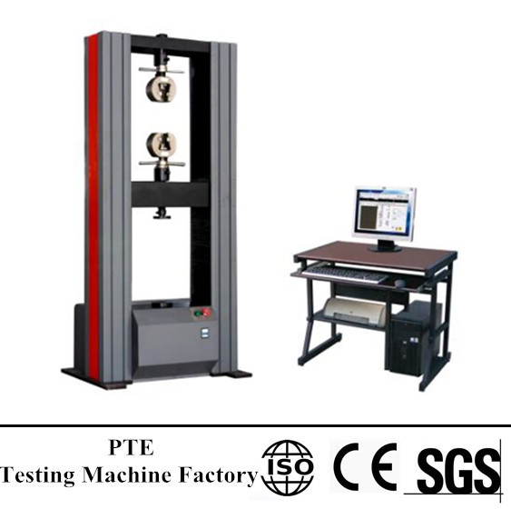
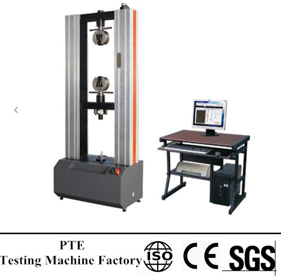
DESCRIPTION OF UTM
The Universal Testing Machine consists of two main parts, idest. imperium panel, et unitas in loading.
THE LOADING UNIT
The loading unit consists of a robust base at the centre of which is fitted the main cylinder and piston. Rigidum frame minus constans est in mensa, the upper cross head and the two straight columns is connected to this piston through a ball and socket joint. A pair of screwed columns mounted on the base pass through the main nuts to support the lower cross-head. This cross head is moved up or down when the screwed columns are rotated by a geared motor fitted to the base. Each cross-head has a tapering slot at the centre into which are inserted a pair of racked jaws. These jaws are moved up or down by the operating handle on the cross-head face and is intended to carry the plate (tenaci) jaws for the tensile test specimen. An elongation scale, which measures the relative movement between the lower table and the lower cross-head, is also provided with the loading unit.
THE CONTROL PANEL
The control panel contains the hydraulic power unit, the load measuring unit and the control devices.
1. The Hydraulic Power Unit.
The Hydraulic Power Unit consists of an oil pump driven by an electric motor and a sump for the hydraulic oil. The pump is of the reciprocating type, having a set of plungers which assures a continuous non-pulsating oil flow into the main cylinder for a smooth application of the test load on the specimen. Hydraulic lines of the unit are of a special design to enable them to perform various functions.
2. The Load Measuring Unit.
The load measuring unit, in essence is a pendulum dynamometer unit. It has a small cylinder in which a piston moves in phase with the main piston under the same oil pressure. A simple pendulum connected with this small piston by a pivot lever thus deflects in accordance with the load on the specimen and the pivot ratio. This deflection is transmitted to the load pointer which indicates the test load on the dial. The pivot lever has four fulcrum -knife-edges, giving fo4ir ranges of test load, (idest. 0-100 kN,; 0-250 kN,; 0-500 kN and 0-1000 kN,). The required range can be selected by just turning a knob provided for the purpose. The overall accuracy of the machine depends mainly on the accuracy of the measuring unit.
3. Control Devices.
These include the electric control devices, the hydraulic control devices and the load indicating devices.
The Electric Control Devices are in the form of four switches set on the left side of the panel face. The upper and lower push switches are for moving the lower cross-head up and down respectively. The remaining two are the ON and OFF switches for the hydraulic pump.
The Hydraulic Control Devices are a pair of control valves set on the table or the control panel. The right control valve is the inlet valve. It is a pressure compensated flow control valve and has a built-in overload relief valve. If this valve is in the closed position, while the hydraulic system is on, oil flows back into the sump. Opening of the valve now, cause the oil to flow into the main cylinder in a continuous non-pulsating manner. The left control valve is the return valve. If this valve is in the closed position, the oil pumped into the main cylinder causes the main piston to move up. The specimen resists this, movement, as soon as it gets loaded up. Oil pressure inside the main cylinder (and elsewhere in the line) then starts growing up until either the specimen breaks or the load reaches the maximum value of the range selected. A slow opening of this valve now causes the oil to drain back into the sump and the main piston to descent.
operantes in apparatus universae temptationis
Maybe etiam tibi
 universae tentationis machina working
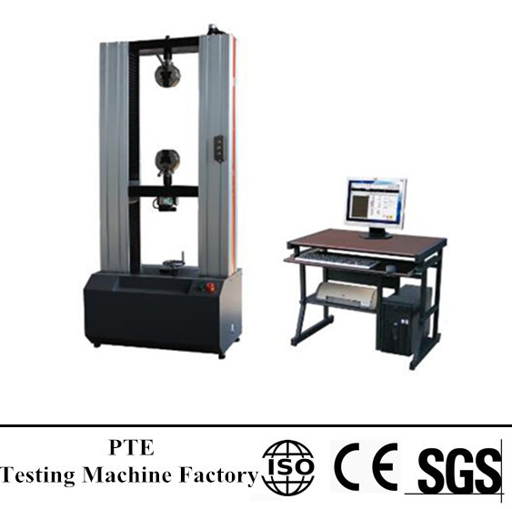 quid sit tentantes universae machina
© effingo MMXVII | Sinis tentationis machina manufacturers| Quisque vestibulum